Chapter 6. INSTALLATION
- Table of Contents
- PU Connections
- Location
PU Connections
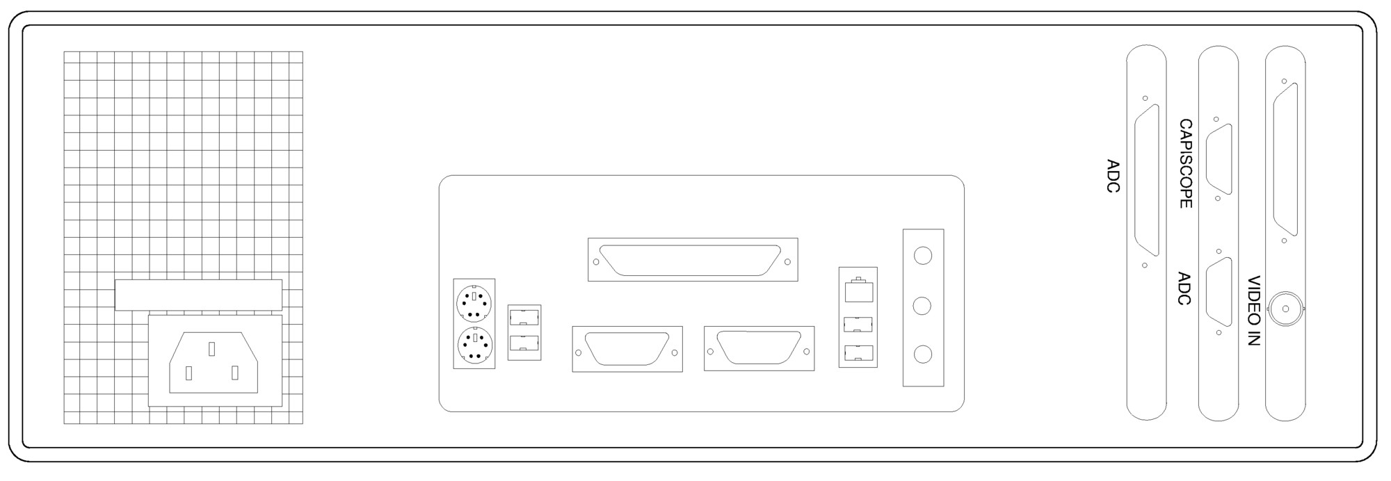
There are two connectors on the interface card: a 9 pin "CapiScope" and a 25 pin "ADC". The top "CapiScope" connector provides the control and CAM1 inputs. The CAM1-PU lead with the single male 9 way connector fits here. The two connectors on the other end fits to the CAM1 probe and the CCD camera 'DC IN/SYNC'.
| Warning |
Do NOT use any other cable to extend the cable supplied with the CAM1. Doing so WILL damage the CAM1, the PU and also the interface board. Although the connectors are the same type as used for serial RS232 cables, the internal wiring from to connector to connector is different. |
The other 25 pin "ADC" connector on the interface card provides output of the Doppler signal for the ADC card. A short ADC-ADC cable connects the two "ADC" connectors.