Video Tools
Selecting Video
Many of the video sequence tools work either on the whole video sequence or only a selected part of the video.
To select only part of the video, use Edit, Select images. Enter the image number of the first, START and last, END image.
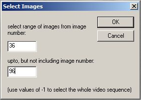
Image numbers are displayed in the status box. Values of -1 will use first and last image for START and END respectively.
Functions which process and change the video images will not destroy the original video data but create a new .mve video file. If START and/or END are set, then the resulting .mve file will be shorter than the original. Further processing with new START or END values will only overwrite the selected video frames.
Saving the file will mark the .mve file as original and the previous paragraph will apply again.
If Settings, compress video output is enabled, then all video processing functions will create a new .avi file each time. i.e. CapiScope cannot process and overwrite just the selected portions of .avi files.
Trimming video ( Deleting images )
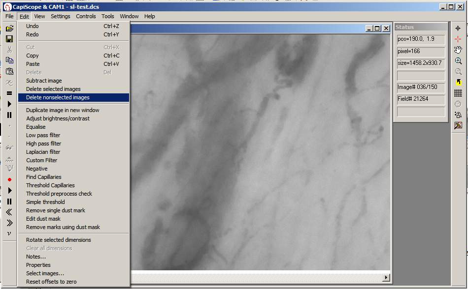
Either the currently selected part of the video can be cut, or the video can be trimmed down to just the selected portion. Select the range as described above then use Edit, Delete selected images, or Delete nonselected images.
Average Whole sequence
Will create a new image with an average of the video sequence from START to END. If movement correction has been used, then the new image will be larger to include all movement.
Useful for sparsely filled capillaries.
Movement Correction
Movement artefacts in video sequences can be corrected either automatically, or manually by dragging the mouse. Individual images, selected images, or the whole video sequence can be corrected.
Although good results can be obtained, it always much better to try and make sure there is no movement in the first place, especially if velocity measurements are going to be made. See Calculate Movement Correction
Functional Capillary Density and Flow  
This is an experimental measurement which produces an image proportional to velocity. It is dependant on image contrast and relies on movement in the vessels such as gaps and white cells. It is calculated using similar processing as in laser Doppler blood flow monitors/imagers, but using the grey level fluctuation at each pixel position instead of laser Doppler shift.
You need very stable video for this to work well. Use the  automatic movement correction function first. See Calculate Movement Correction
This function uses either the whole video sequence or the selected image range.
If there is large movement or drift, it is recommended to split the fcf calculation into smaller video segments.
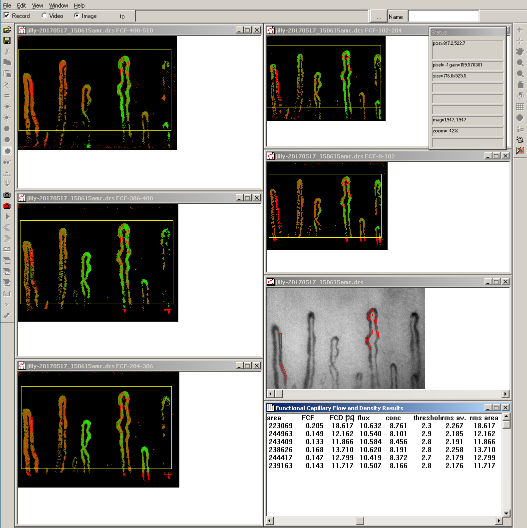
Long video recordings can be split into a series of smaller segments. Enter the number of frames to use for each separate segment,
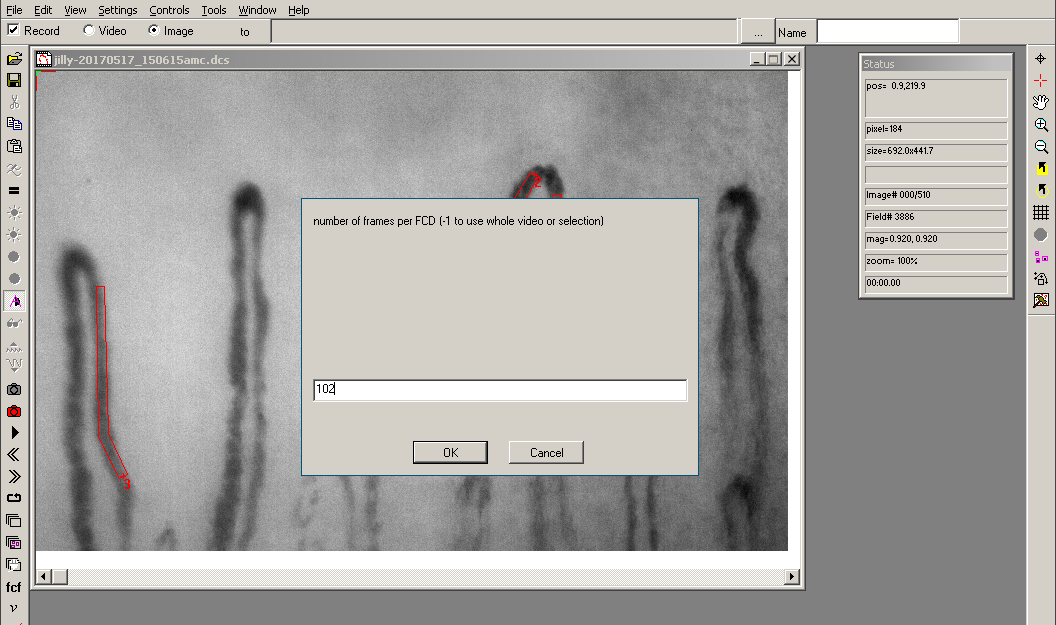
or enter -1 to use the whole video selection.
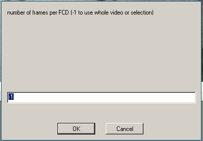
For each fcf calculation, a ROI will be drawn selecting the area that is common to all images in the video segment. If there is so much movement that there is no common area, no ROI will be drawn and the results will use the whole image area.
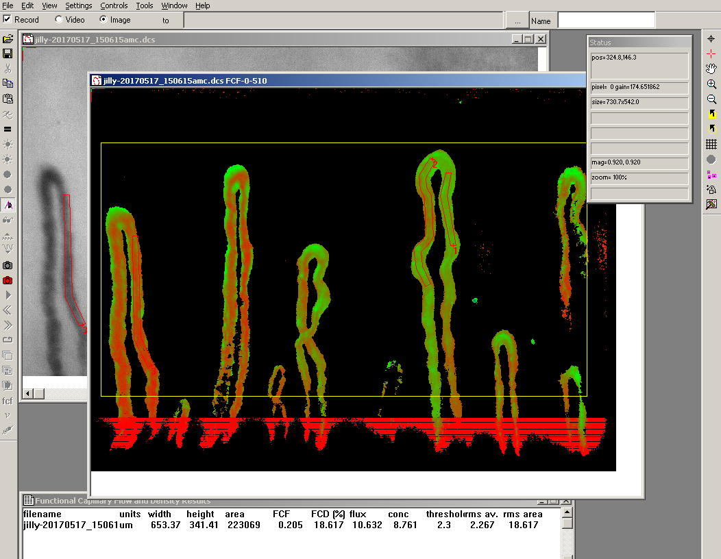
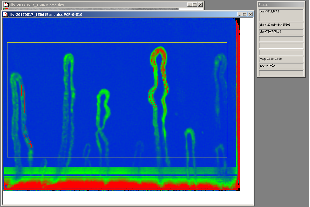
A FCF document contains the FCF, Flux, Conc, and Mask floating point double images. By default the FCF image is copied and displayed as an 8 bit image. You can select which image is copied to be displayed in the View menu. Images are copied to the display using the current gain setting.
Example using the whole video sequence (510 images)
Example using five segments of 102 images
Threshold
By default, the threshold is calculated automatically.
Use the F3 and shift F3 function key to shift the threshold up and down. This will also disable automatic threshold.
To find a suitable threshold level manually, draw a small ROI (yellow box) say
35x35 (you can see the size in the status box as you draw). You can drag
this box onto a vessel with flow then click = or  .
.
Note the conc value.
Drag the same ROI box into a obviously non-vascularised area. Press
= or  .
.
Note the new conc value.
Take the average of the 2 values .
Choose the menu controls, recalculate and enter the average for the threshold and click ok.
Draw ROI and press = or  to get values for functional flow and density.
FCF Functional Capillary Flow
FCF = Flux / Conc in arbitrary units. This is calculated pixel by pixel where the rms mask or conc value is greater than or equal to the threshold. Pixels where the rms mask or conc is less than the threshold are set to zero.

FCD Functional Capillary Density
Density of detected functional capillaries / area of ROI as a percentage. Detected functional capillaries are where the rms mask or conc value is greater or equal to the threshold value. Pixels where the rms mask or conc is less than the threshold are set to zero.
Flux
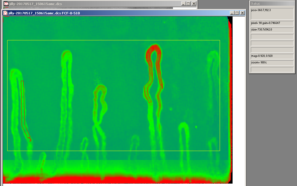
Calculated per pixel, this is
flux = rms of differential of grey level against time in arbitrary units
- See
Watkins and Holloway laser Doppler flux monitor. Watkins, D. W. and Holloway, G. A. (1978) An instrument to measure cutaneous blood flow using the Doppler shift of laser light. IEEE Trans., BME-25, 28–33.
Conc
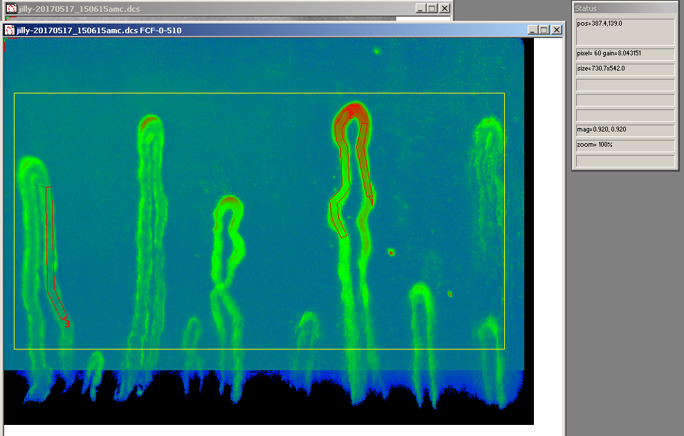
Calculated per pixel this is
conc = rms of grey level against time in arbitrary units
rms MASK
Calculated per pixel this is
mask = rms of grey level against time in arbitrary units
The mask is also filtered to remove image sensor noise.
Recalculate
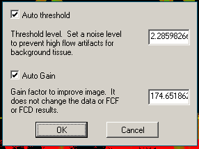
Use the Recalculate function in the Controls menu. A dialog box will prompt for the threshold value to use, and a gain factor. The gain factor is used to scale the current array into a 8 bit (0-255) image for display only.
By default automatic gain and automatic threshold are enabled.
View FCF,Flux,Conc, or Mask
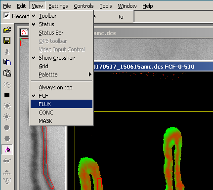
Use the View menu to show the flux,conc or mask images. FCF is displayed by default and after recalculating.
The gain for the current image is shown in the status box.
Use Mask or Conc for threshold
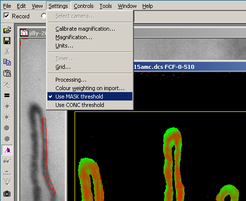
Use the settings menu to switch using the conc or mask image for thresholding capillaries. Default is to use the mask image.
Nailfold Panorama
There is a new toolbar button on the right hand toolbar under the “tools” button.
It will perform a “movement correction” which can take some time, then produce two images. The first is a panoramic image using only the sharpest image for each region. The second averages all images.
If you’ve already done the movement correction and just want to produce the panoramic image, use the menu “tools”, “average all in focus”. You’ll be asked for a value which defines the region size used to find the best focus. Minimum is 2, default is 5. Higher=smaller region. This value is saved for all subsequent averaging.
Use menu “settings”, “focus measurement settings”, “enable” to show the focus value in the status box for each image.
You can produce a chart of the focus and x,y movement using ctrl-w “focus check video”
Flying Spot  
Use the  loop play toolbar button to play the video in a
continuous loop and draw a dimension line next to the vessel.
Click on the flying spot toolbar button.
A dimension line needs to be selected, and the currently selected line will have the flying spot.
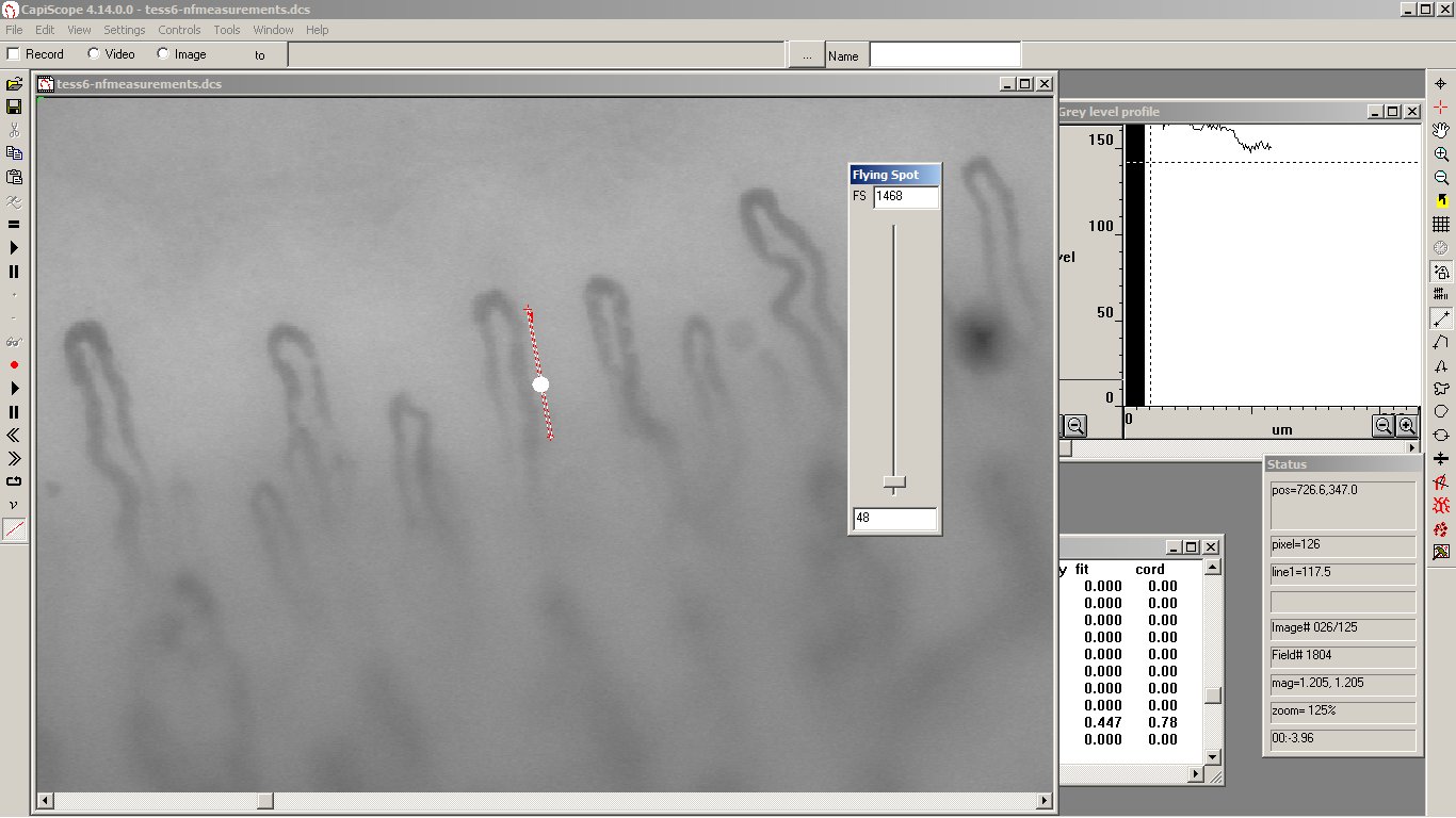
Use the flying spot slider to adjust the velocity of the flying spot. Whilst the slider is being adjusted, the flying spot velocity is saved for each frame. The flying spot velocity can be continuously adjusted throughout the video.
Corrective adjustments can be made by readjusting the slider at any point. If you “let go” of the slider it will use the previous velocity set for each frame (initially zero).
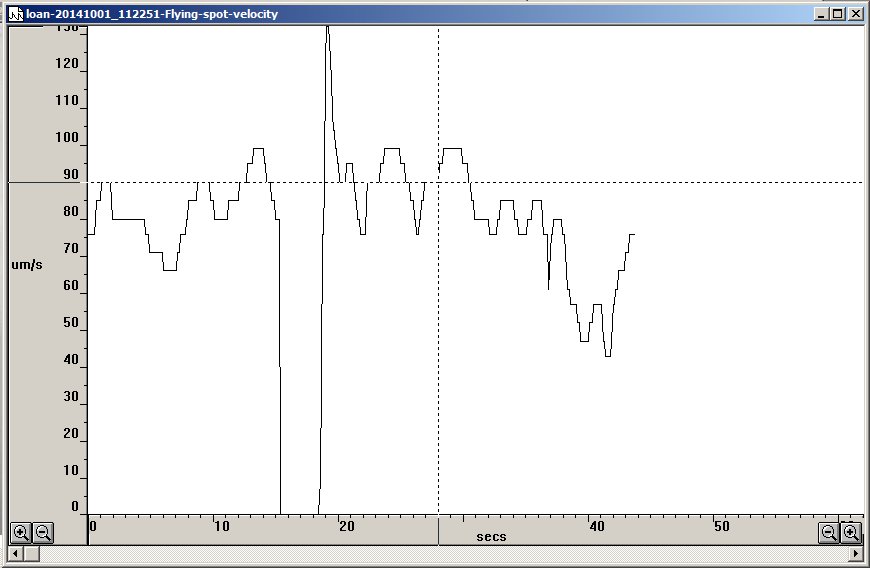
Use the Tools menu “Chart flying spot velocities” to show the flying spot velocity over time. The velocities are saved with the video sequence. There is only one velocity recording irrespective of the number of dimension lines.
Compress Video Output
In the Settings menu use the compress video output option to cause all video output to disk ( live recordings, processing and file saves ) to be compressed. This requires the x264vfw CODEC to be installed.
To avoid the first 90 odd frames from being blank, change the x264vfw CODEC default configuration. Check the Zero Latency check box.
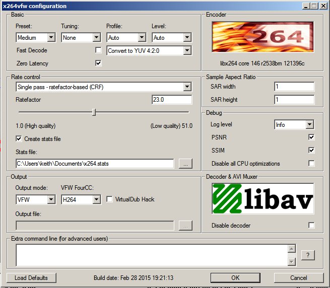
You can also change the compression quality etc, but the default settings work very well.
Note
CapiScope version 4.53
